AUDIO ROUTER BEA3X
BEA3X-GPIO Audio Card Bea3x

BEA3X-GPIO: Versatile I/O Solutions for Audio Systems
Exploring 12 GPOs and 12 GPIs with Flexible Configurations
The BEA3X-GPIO card, featuring 12 General Purpose Outputs (GPO) and 12 General Purpose Inputs (GPI), is a versatile audio system component. With two DB26 connectors, it provides a wealth of connectivity options.
GPOs are equipped with central relays, normally open contacts, and configurable normally closed contacts. The card’s software-driven logic customization offers unmatched flexibility.
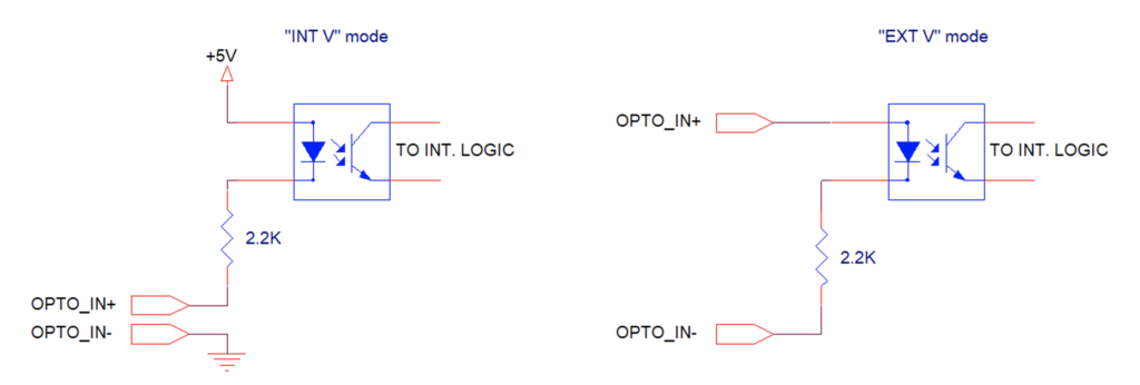
GPIs come with “Int V” and “Ext V” modes, selectable through jumpers on the board. In “Int V” mode, they use a 5V bias and activate upon contact closure with minimal current. In “Ext V” mode, external DC voltages within the 5V to 48V range activate the GPIs.
This adaptability enhances your audio system’s capabilities for various applications.
- Versatile I/O
- 12 GPOs
- 12 GPIs
- Flexible Configurations
- DB26 Connectors
BEA3X-GPIO: Expanding Audio I/O Possibilities
Unlocking the Power of 12 GPOs and 12 GPIs with Configurable Options
The BEA3X-GPIO card features 12 GPOs and 12 GPIs, accompanied by two DB26 connectors.
GPOs come equipped with a pair of contacts for each, including the central relay and the normally open contact. For two GPOs, the normally closed contact is also accessible via configurable pins. Notably, the logic for all relays is fully customizable through software.
GPIs offer a pair of contacts that can be either short-circuited or externally powered, depending on the configuration set through the board’s jumpers.
Two GPI modes are available, namely “Int V” and “Ext V,” with each GPI configurable using three jumpers indicated on the PCB. In “Int V” mode, GPIs bias their pins with 5V and activate upon closing the pair with an external clean contact, drawing a current of approximately 2mA. Conversely, GPIs configured in “Ext V” mode lack bias and require an external DC voltage within the range of 5V to 48V to activate.
This card offers extensive flexibility and customization options for a wide range of applications.
The simplified schematics for the two modes are these:
Pinout DB26 #1
Discover the detailed pinout information and explore the values associated with DB26#1, ensuring seamless connectivity and enhanced functionality.
| Connector 1 | Pin | Note |
|---|---|---|
| C-GPO1 | 1 | Common contact relay 1 |
| O-GPO1 | 2 | Normally Open contact relay 1 |
| C-GPO2 | 3 | Common contact relay 2 |
| O-GPO2 | 4 | Normally Open contact relay 2 |
| C-GPO3 | 5 | Common contact relay 3 |
| O-GPO3 | 6 | Normally Open contact relay 3 |
| C-GPO4 | 7 | Common contact relay 4 |
| O-GPO4 | 8 | Normally Open contact relay 4 |
| User defined 1 | 9 | User defined +12, +5, GND, Normally Closed 4 |
| C-GPO5 | 10 | Common contact relay 5 |
| O-GPO5 | 11 | Normally Open contact relay 5 |
| C-GPO6 | 12 | Common contact relay 6 |
| O-GPO6 | 13 | Normally Open contact relay 6 |
| C-GPO7 | 14 | Common contact relay 7 |
| O-GPO7 | 15 | Normally Open contact relay 7 |
| C-GPO8 | 16 | Common contact relay 8 |
| O-GPO8 | 17 | Normally Open contact relay 8 |
| User defined 1 | 18 | User defined +12, +5, GND, Normally Closed 8 |
| C-GPO9 | 19 | Common contact relay 9 |
| O-GPO9 | 20 | Normally Open contact relay 9 |
| C-GPO10 | 21 | Common contact relay 10 |
| O-GPO10 | 22 | Normally Open contact relay 10 |
| C-GPO11 | 23 | Common contact relay 11 |
| O-GPO11 | 24 | Normally Open contact relay 11 |
| C-GPO12 | 25 | Common contact relay 12 |
| O-GPO12 | 26 | Normally Open contact relay 12 |
Pinout DB26 #2
Discover the detailed pinout information and explore the values associated with DB26#2, ensuring seamless connectivity and enhanced functionality.
| Connector 2 | Pin | Note |
|---|---|---|
| 1-GPI1 | 1 | Contact 1 Opto 1 |
| 2-GPI1 | 2 | Contact 2 Opto 1 |
| 1-GPI2 | 3 | Contact 1 Opto 2 |
| 2-GPI2 | 4 | Contact 2 Opto 2 |
| 1-GPI3 | 5 | Contact 1 Opto 3 |
| 2-GPI3 | 6 | Contact 2 Opto 3 |
| 1-GPI4 | 7 | Contact 1 Opto 4 |
| 2-GPI4 | 8 | Contact 2 Opto 4 |
| User defined 1 | 9 | Can be assigned to +12, +5, GND |
| 1-GPI5 | 10 | Contact 1 Opto 5 |
| 2-GPI5 | 11 | Contact 2 Opto 5 |
| 1-GPI6 | 12 | Contact 1 Opto 6 |
| 2-GPI6 | 13 | Contact 2 Opto 6 |
| 1-GPI7 | 14 | Contact 1 Opto 7 |
| 2-GPI7 | 15 | Contact 2 Opto 7 |
| 1-GPI8 | 16 | Contact 1 Opto 8 |
| 2-GPI8 | 17 | Contact 2 Opto 8 |
| User defined 2 | 18 | Can be assigned to +12, +5, GND |
| 1-GPI9 | 19 | Contact 1 Opto 9 |
| 2-GPI9 | 20 | Contact 2 Opto 9 |
| 1-GPI10 | 21 | Contact 1 Opto 10 |
| 2-GPI10 | 22 | Contact 2 Opto 10 |
| 1-GPI11 | 23 | Contact 1 Opto 11 |
| 2-GPI11 | 24 | Contact 2 Opto 11 |
| 1-GPI12 | 25 | Contact 1 Opto 12 |
| 2-GPI12 | 26 | Contact 2 Opto 12 |
Contacts specification of the card
| Max GPO current | 1A |
| Max GPO voltage | +/-50V referred to GND |

